==============
Support rules and bridges drawings
Generating bridges drawings for individual support tools
Using smaller-sized dieboards from waste materials
Individual support tools drawings
==============
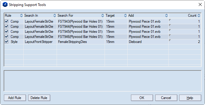
Support tools are generated according to pre-defined rules. A rule exists for the generation of the respective support tool for each component type from the set of stripping drawings. Consider the following example.
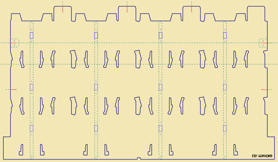
In a FemaleStrDie drawing, we have used the same component for the positioning of the holes necessary for the mounting of support bars:
The same support tool rule (indicated in the Rule column) will apply to all four sets of holes:
As a result, four bars will be generated in a single drawing.
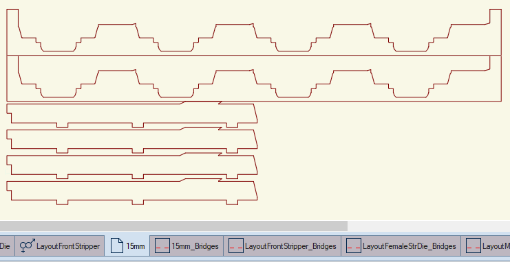
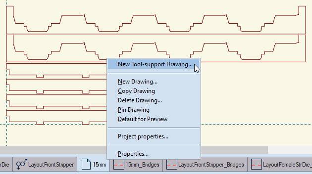
In the next step we generate the bridge drawings for all the drawings related to the stripping system.
 .
.The program detects all automatically generated stripping drawings — LayoutMaleStrDie, LayoutFemaleStrDie, LayoutFrontStripper, or all support tool drawings, in the current case, drawing "15mm" — and creates a bridge drawing for each one of them.
Quite often, die manufacturers use smaller-sized dieboards made from waste materials to cut support tools. In this technology, it is a handy solution to have each support tool in a separate drawing, and, as a result, to create a bridge drawing from each of these drawings.
There are two approaches to separate each design in a separate support tool drawing:
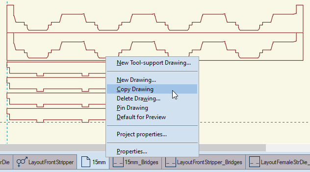
The program copies the drawing, and adds it to the left of the existing drawings on the taskbar.
The New Drawing dialog box appears.
The program creates a new drawing.