 .
.The design of a counterplate begins in the 1up. In it, markers are placed which ensure the correct positioning of the counterplate with regard to the cutting die. Then the counterplate design process begins (in a separate drawing).
NOTE ON COUNTERPLATE PROCESSING SIDES: Counterplates are always viewed from their front side, regardless of which side the original 1up is viewed. The counterplate's front side is set for the material from which the counterplate is made. If you choose to change the view side of the counterplate, after the change, click Refresh .
Video: Designing counterplate
![]() Click the icon to watch the video. Runtime: 1:33 min.
Click the icon to watch the video. Runtime: 1:33 min.
To design a counterplate
 .
.A contextual edit bar appears above the graphical area.

NOTE: Package Designer is installed with two default counterplate marker (CPM) components: CPM Circle and CPM. These are editable parametric components. You can create further components and add them to the list. (These are parametric components which can be created and modified with EngView Synergy.) By default, the components are installed in \\EngViewWork7\Settings\Features\CPMarkers.
When you have selected a component, it appears at the mouse pointer as you move the mouse.
A 1up drawing with inserted markers
NOTE: After the markers have been placed, they will appear also in the Layout drawing, and will be automatically added during the generation of the Bridges drawing and the CAM drawing.
The Counterplate Generation Options dialog box appears.
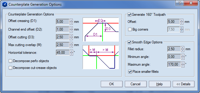
Counterplate Generation Options Settings that define the counterplate contour.
Offset creasing (D1) Sets the offset of the counterplate contour from the creasing lines. Indicated with D1 in the image.
Channel end offset (D2) Sets the offset that the counterplate contour will have at the point where the creasing channel meets the cutting line. Indicated with D2 in the image.
Offset cutting (D3) Sets the offset that the counterplate contour will have in relation to the cutting lines. This is the minimal offset from the cutting contour. If the D3 value is smaller than the difference between D1 and D2, it is ignored. If the D3 value is greater than the D1–D2 difference, the program generates the counterplate contour according to the D3 value.
Max cutting overlap (M) Sets the maximal distance that a cutting segment may have to coincide with the counterplate contour. If the cutting contour is longer than the M value, the counterplate contour is set at an offset.
Horizontal tolerance Sets the maximal angle at which a creasing object may lie askance from the x-axis and still be treated as horizontal.
Decompose perfo objects Turns objects in the Perforating style into individual objects in the Cutting style which are separated by blank spaces. These objects are then taken into account during the generation of the counterplate.
Decompose cut-crease objects Turns objects in the Cut-Crease style into individual alternating objects in the Cutting and Creasing styles. These objects are then taken into account during the generation of the counterplate.
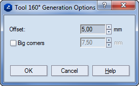
Generate 160° Toolpath Determines the path of the filleting tool.
Offset Sets the offset for the 160-degree filleting tool.
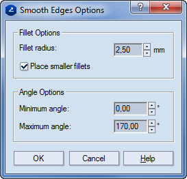
Smooth Edge Options Settings that control how the counterplate's edges will be rounded.
Fillet radius Sets the radius for rounding the edges.
Min. angle Sets the minimal angle to be rounded.
Max. angle Sets the maximal angle to be rounded.
Place smaller fillets If necessary, performs roundings with a radius smaller than the one set in Fillet radius.
A Counterplate drawing appears.
 is not pressed in.
 .
.NOTE: Do this operation if you did not use it in the original counterplate generation (see Step 4) or if you have made manual changes to the counterplate contour (see Step 6).
The Smooth Edges Options dialog box appears.
 , and in the dialog box that appears enter an offset value.
NOTE: Do this operation if you did not use it in the original counterplate generation (see Step 4) or if you have made manual changes to the counterplate (see Step 6).
The 120-degree and the 160-degree tool paths are visible.
NOTE: Generally, when a set of counterplates is necessary, a layout of the counterplate design is generated, which is then cut through CAM.
 .
.