Defining CAM templates: CAM Tools
EngView CAM tools drive machine instruments. Click
here to learn more about them.
What are CAM tools
In Prinect, CAM tools
are representations of how the physical instrument on the sample-producing
machine processes the objects as they come from the 1up drawing. Because
of this, wherever in this document you read "CAM tool" or
"tool", read it as "instrument processing mode".
You define a CAM tool by setting the properties that you want the
instrument to process. defined by properties that
Types of CAM tools
CAM tools can be:
- Primary. This is the processing mode that the instrument
uses most often.
- Child. A child tool is a modification of its parent
primary tool. Normally, it has most of the primary tool's properties
and settings, but some of its settings have been modified to serve
specific functions. For example, You can create child tools only
for an existing primary tool.
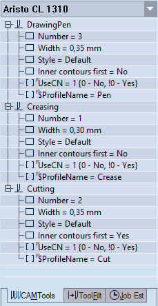
Where can I see them?
How CAM tools process tool paths
CAM tools process the tool path in the top-down
order in which they are sorted in the CAM template. The tool path
of the topmost tool is generated first, followed by the tool path
of the one below it, and so on. Prinect generates
separate optimized tool paths for each of the primary CAM tools and
processes these tool paths according to the top-down order in which
the tools are defined in the CAM template: the tool path of the topmost
tool is generated first, followed by the tool path of the one below
it, and so on. Prinect then links
the individual tool paths.
You might need to processes section of a
tool path with properties whose values are dfferent from those in
the primary tool. In this case, you create child tools. These inherit
the majority of the properies and their values of the parent tool,
but different values for others. Child tools appear directly below
their parent primary tools in the tool tree and are processed immediately
after them. Consider two examples: Example 1: A laser beam used for
cutting a dieboard may be used also for engraving the bridges along
the tool path. This removes the necessity of removing and readjusting
the beam, and then running it again along the tool path. By using
a child tool — which is a different mode of processing — an instrument
processes the same tool path in different work modes. Example 2: A
cutting tool can be used for cutting through a design completely and
also for executing half-cuts as in kiss cuts.
How do I define CAM tools?
NOTE: The procedure that follows tells
you how to create both primary and child CAM tools. To create a child
tool, in the tree structure in the left area, click a primary tool, and
then click New Tool Then proceed with defining the child tool.
======================
======================
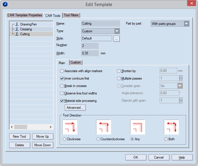
Name Type a name for the tool. It will appear (1) in the
tree structure on the right and then (2) in the CAM Tools tab of the CAM
drawing.
Type Set a type for the tool. Preset types include Router,
Laser beam, Water jet, Cutting knife, Creasing wheel, V-cut, Matt cut,
and Pen. Custom lets you set your own type.
Style Click the browse button  to select
the style of the objects that the instrument will process.
to select
the style of the objects that the instrument will process.
NOTE: "Default" means that no
style is selected. Use "Default" if you want to set a color
to a certain object type. This will not associate the instrument with
any particular style.
Number Type the number of the tool as corresponding to
the consecutive numbers of the instruments on the actual machine. NOTE:
You can change the tool number later, when you generate the NC script
file in the NC Generation Properties dialog box.
Width Set the physical width of the processing tool.
Part by part (Applies for CAM drawings generated
from layout drawings for which the part-by-part
processing rule has been set.)
Before part groups The tool will process the objects associated
with it — in the layout parts and those placed additionally — before processing
all other objects. NOTE: If this option is set for multiple tools in the
CAM
template, Prinect starts
one tool at a time in the top-to-bottom order set in the template.
With part groups The tool will process the objects associated
with it according to the part-by-part
processing rule. Objects placed directly in the layout drawing (they
do not belong to any layout part) will be processed last, after the objects
in the layout parts have been processed.
After part groups The tool will process the objects associated
with it — in the layout parts and those placed additionally — after all
other objects have been processed. NOTE: If this option is set for multiple
tools in the CAM
template, Prinect starts
one tool at a time in the top-to-bottom order set in the template.
The Main tab
Associate with align markers Associates the tool with align
markers, if such have been placed. Such can be, for instance, cut or creased,
depending on the tool with which they are associated.
Inner contours first Generates a tool path for which the
current tool starts from the inner objects. For example, if you make a
CAM sample of a packaging box with an inscribed ellipse in one of the
sides, cutting the outer contours first would leave the cutting of the
ellipse for the end of the tool path. As a result, the sheet will not
hold steadily on the samplemaking machine.
Break in crosses (Applies to the points where different
objects intersect.) To produce the optimal tool path, Prinect may choose
to shift the tool path's trajectory at the point where two objects intersect.
Observe line/width tool widths Takes into account the difference
in width between a tool whose width is smaller than the width of the object
to be processed, and makes additional runs of the tool so that the necessary
width is processed. For example, if the object is 6pt wide and the tool's
width is 2pt, the width of the resulting object will be less than the
6pt needed. In this case, the tool will make additional runs to process
the needed 6pt width.
Material side processing Sets properties for processing
of the material. These include (1) the side on which the cutting will
be done, (2) the lead-in and lead-out settings, and (3) the directions
of processing for the inner and outer sides. To edit these settings, click
Advanced, and then use the dialog
box that appears.
Shorten by Shortens the creasing objects by a certain distance,
so that the creasing wheel stops before it reaches the end of a creasing
lines. This prevents damaging creasing regions that lie next to creasing
lines. In the edit box on the right, enter the distance, in the current
metric units, by which you want to shorten the creasing objects.
Multiple passes The processing instrument performs several
passes on creasing objects. Enter how many times you want the creasing
instrument to pass along these objects. Value range: [0–3]. TIP: This
technique is very useful when processing a harder material. The creasing
objects are processed several times by the creasing instrument, which
ensures that later they are easier to fold. Type how many times you need
the instrument to pass along a tool path section. You can make the Prinect visualize
in how many times the instrument has passed along a tool path section
(use the Multi-pass count marker check box).
Consider grain Sets if the grain direction goes along the
x-axis or the y-axis.
TIP: When choosing the grain direction,
consider how the sheet is placed.
Angle tolerance Sets the maximal angle by which the creasing tool
should be allowed to veer off from the grain direction as measured against
the horizontal and vertical axes.
Objects with grain Sets a special number of creases for
the objects processed with grain direction. Usually this number will be
smaller than the number in Multiple crease. In this way, you can
use a different number of passes for the creasing objects processed along
the grain and the ones processed against the grain. Value range: [0–3].
Tool Direction
Clockwise Processes the outside contour clockwise.
Counterclockwise Processes the outside contour counterclockwise.
Any Lets Prinect choose
the processing direction — clockwise or counterclockwise.
Both Processes the contour both clockwise and counterclockwise.
Editing V-Cut settings
Settings for V-Cut jobs differ from those for
the other CAM instruments.

Tool Direction
Any. Optimizes the tool path automatically. To set the channel
depth, click the Custom tab. NOTE: The reverse V-Cut move does not need
to follow immediately the forward one.
Both. The machine carries out both the forward and the reverse
moves.
The Custom tab. You create the properties in this tab while you are setting the properties
of the machine. Here you can only edit their values as you need them
for the job in hand.
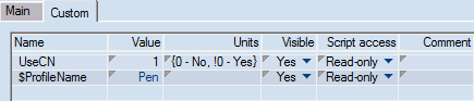
Name (Read-only) Displays the name of the custom property.
Check the custom properties that you want the child tools to inherit from
their primary tools.
Value Sets the value of the property.
Units Sets the measurement units of the value.
Visible Tells EngView whether to display the property in
the tabular area of the CAM Tools tab. The options are "Yes"
and "No".
Script access Sets how the script will handle the tool's
Value setting. The options are:
| Read-only |
The script uses the value of the property as it is defined
in the CAM template. No changes are made to it during the job. |
| Local Only |
During the job, the script dynamically makes changes to the
value of the property. These changes are lost after the job has
been completed. |
| Committable |
During the job, the script dynamically makes changes to the
property value. When the job is completed, the changes are saved
to the CAM template and apply to the next job. |
Comment (Optional) Type any relevant information about
the property.
Tool Optimzation (glass engraving)
You can make each instrument begin its course from the machine's starting
point. That is, when a tool has completed its course, the next tool starts
again from the machine's starting point, not from the nearest point of
the course of the next tool. Although the route that the instrument covers
is longer and may take more individual passes, it ensures greater precision.
This technique is especially applicable in glass engraving, as it ensures
highest-quality processing.
To reset the tool optimizer, create a custom property in the Custom
tab.
| Custom property and value |
What it does |
| StartFromZeroPoint = 0 |
The next tool starts from the point that's nearest to where
the last tool completed its course. |
| StartFromZeroPoint = 1 |
Each tool starts from the machine's starting point. |